Some might ask me how I manage to use an indexing valve on my big system CHIFT PIST set up when my pump runs constantly. Well this might not be the best layout for using an indexing valve but I’m managed to make it work.
I designed a low pressure aquaponics automated valve that can still work with only about 18 inches of water column. The indexing valve in question has a gravity modified stem and with a huge flow of water with that 18 inches of water column it has been working well for about a year and a half.
Many people might ask me why I don’t simply use a solenoid valve. Well the answer to that is most irrigation solenoid valves require quite a large differential pressure to operate (the pressure required if supplied by gravity would have me placing the fish tank on top of the roof in order to get enough pressure to work the valve.) And I don’t know if a regular solenoid valve would keep working well with the slime from an aquaponics system.
Building your own low pressure aquaponics automated valve is possible for the DIY person with experience in plumbing and electronics.
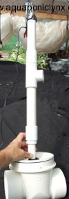
Essentially the valve is made up of three primary parts.
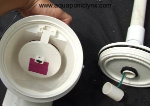
1-backwater valve installed backwards
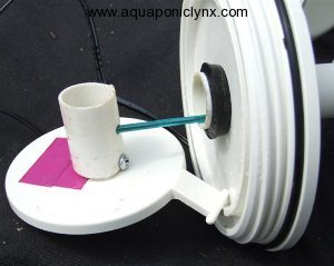
2-car door actuator to pull the valve open and closed
3-electronic controller to trigger the opening, closing and timing of the valve.
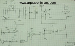
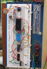
This is the original timer circuit to control the automation that a friend helped me with I have since had a better circuit made that uses a chip to control the timing rather than an RC circuit but this original timing circuit did work just fine.
Finally, I never quite got rid of the bounce problem and even with a spring ball latch, I still need to have the rubber band in place and it needs to be replaced every few months. That is my low pressure aquaponics automated valve. I’m rather proud of it.







Oh boy, I have no confidence that I could ever pull this off 🙂
I love the idea of using an indexing valve, but like you, I wouldn’t want to resort to using failure-prone timers for my pump(s). So this valve interrupts the flow proximal to the indexing valve, correct? It would seem that the timing of this interruption would be critical if your grow beds used bell-siphons as the draining mechanism, as you wouldn’t want to interrupt the flow before the siphon had been activated. Do your beds use siphons, or does the use of the indexing valve eliminate the need for them?
Just for an example, what is the time period that this valve is set for, and how do you change the timing of it?
Thanks for the feedback….Jeff
This valve is only needed because this particular system is constant height in fish tank and the water flowing from the fish tank to the valve is under gravity pressure and the pump runs constantly as it is an inline pump installed in a way that would not be good to turn the pump on and off all the time.
So I had to develop a way to stop and start the flow of water to the indexing valve that could be automated and still work under fairly low pressure yet allow a large flow rate through it.
This valve and it’s related electronics is actually a possible failure point and I would not use it if a simple timer would work instead. Timers don’t have to be failure prone, just don’t get the really cheap indoor mechanical timers and protect the timers from the sun or water splashing on them.
No, I don’t use siphons on beds fed by an indexing valve. I use stand pipes with some small holes around the bottom and the effect is like timed flood and drain for each bed getting fed by the indexing valve. The important factor is is make sure the valve floods each bed long enough for them to fully flood or even longer (it is ok for the water to flow over the top of the stand pipe for a bit before the timer causes the flow to stop and switch to the next bed when it starts again.)
This particular valve is controlled by the electronic timer. Originally by the one in the picture and now by a chip controlled timer that is a bit more accurate. I generally send flow to the indexing valve for about 9 minutes and then stop the flow for a minute and it repeats as long as power is supplied to the timer. I adjust this by re-programing the chip in the timer of my home made versions. Repeat cycle timers can be purchased that have nobs for controlling the on/off timers, others require watching a light flash and pushing a button appropriately to re-program a chips (kinda tricky but that is what I’m doing on the current controller for the low pressure valve.)
Thank You.
Nice work. Wondering about that bounce problem. To you mean the flapper in the valve would bounce up and down without the rubber band? I am guessing this is with the valve open as the water would tend to try to push it shut.
My guess is that the small piece of pipe you have attached to the backside of the flapper with a screw that has the green cable(?) attached to it is preventing the flapper from traveling to its designers fully open position. Which I am guessing is when the little plastic block on the flapper is up against the top lid.
Did you try just drilling a hole through the middle of the flap and putting the cable through it? I see some purple tape(?) there. I am guessing this did not work as it would not provide the mechanical advantage the small pipe you have attached to the back does.
My guess is to solve the bounce problem you would need to attach your cable as close to the bottom edge as possible without causing a sealing problem. The move your pipe with your cable to directly over it instead of having in in the center of the cover. I realize this is not a nice place to have it when you need to open it
Make sure to secure your “fancy” cover in the event of a hurricane! 😉
I was interested in the electronics diagram but was disappointed that the resolution of the photo that opened when I clicked on it was the same as the small thumb nail that showed in the post. Maybe you could post a bigger version that the thumbnail would open up when clicked on. That way folks with an electronics background could easily copy your circuit.
The bounce was mainly because the actuator would pull quickly then release the force quickly. The rubber band seems to work. I’ve even done a spring ball catch in it but that doesn’t seem to be catching as well so I put the rubber band back on.
The green cable is actually a covered wire and the riser kinda needs to be at the center to allow for putting the valve together with the wire in place. I have moved the wire to the nub in the middle of the flap instead of using the piece of pipe now and that seems to still allow for a little hinge action while providing the proper angle to work. The actuator only has so much travel so I can’t operate it from the outer edge of the flap anyway.
I suppose a better stepper or actuator motor might make for a more solid operation but it would also cost several times the amount to build. The car door actuators usually cost around $10 US.
I’ll see if I can get you a link to a higher resolution of the diagram, ok here is one Link in BYAP thread. I’m no longer actually using those electronics as I got some one to print me a circuit board and provide the electronics for a micro chip controller for it.
Solenoid valves are great specially when you use them on pneumatic valves. ^
Unfortunately most inexpensive solenoid valves won’t work at low differential pressures normally used in aquaponics. Most of them require about 5 psi at the valve to even function and most aquaponic applications are often seeing less than 1 or 2 psi by the time the water reaches bed level if they are pumping directly to the beds. If water is flowing by gravity to the beds, it is rarely even 1 psi unless the fish tank is up the hill from the beds.